DigiCad 3D

How to eliminate perspective distortion from a building photo

How to eliminate perspective distortion from a building photo

Follow the step bellows:
  • Import a photo
  • Set scale and unit of measure
  • Set the four origin attach points on the photo. The bottom-left point first, the top-left point second, after the top-right and the bottom-right. The Attach points are represented with red markers on the screen.
  • Open the Destination Attach points dialog from the Trasnfrom menu
  • Insert the real coordinates correspondent to the Destination Attach points. The reference system isn't important, it's sufficient that all the coordinates are in the same reference system (ex. the left corner of the building and the ground line). The Destination Attach points are represented with blue markers on the screen.
  • Select the picture
  • Choose Transform Picture from the Transform menu
  • Choose resolution, number of colors and Opaque or Transparent option
  • Click the Ok button
The process requires some time, depending on the picture size, the scale, the resolution and the size of the transformed picture. The message box shows the progress of the process

Is it possible to eliminate perspective distortion from a photo without any measured point?

Is it possible to eliminate perspective distortion from a photo without any measured point?

Yes, it is. This is when you do not have the precise measurements necessary for an exact operation – you have perhaps a few horizontal/vertical indications, which can help reconstruct an approximate situation. In this case, draw on the photo the lines you believe to be horizontal and vertical, put the 4 attach points on the photo and make a rough drawing of lines and attach points. Move the destination attach points until the horizontal and vertical lines are correctly aligned. When you have got the drawing right, you can transform the image. Another method is to draw a rectangle with the approximate final size of the drawing. Set graphically the Destination Attach points on the vertices of the rectangle and the Origin points on the corresponding points on the photo.

How DigiCad 3D’s Attach Functions from files Work

How DigiCad 3D's Attach Functions from files Work

igiCad 3D has various Attach functions, from the File menu, that allow you to "snap together" different drawings by designating a certain number of corresponding Attach Points. A two point attachment is the simplest and allows you to connect two drawings by designating an origin point and reference point (two Attach Points). When the two drawings are attached, or "snapped" together, they are automatically scaled, fitting one drawing to the other. Four and five point attachments are used for maps and architectural surveys using photographs. In the latter case, you can obtain a perfectly scaled elevation using one or more photos of the building face. The common denominator in each of these cases is the use of two documents (the source document - a digitized photo, for example - and the resulting scaled document). For the survey of an architectural facade, the work phases would be as follows: - import the image (drawing or photo) - designate at least 4 Attach Points - digitize all the necessary parts of the image (maybe certain sections aren't needed) - save the work - open a new document - insert the 4 corresponding Attach Points with their real measurements (the four corners of a window, for example, or the four corners of the facade - it depends on the scale of the detail wanted) - Attach the previously saved document using the Attach command. With the new Dynamic Attach feature you can do the same thing using just one document instead of two, controlling the work dynamically and reducing your work time. With the new procedure, the steps are as follows: - import the image - designate the 4 Origin Attach Points and insert their corresponding real measurements in the Dinamic Attach Points - digitize the image and/or transform the picture or parts of the picture. Using this procedure you can view the image you're digitizing AND the corresponding corrected elevation image at the same time, allowing any errors to be corrected immediately. If you move the Attach Points, everything is simultaneously scaled accordingly. The Dynamic Attach procedure doesn't mean, however, that the old "static" procedure is obsolete. In more complex cases where several photos are used (some general, others of details), it is more convenient to work on several separate documents, then snap them all together afterward.

What is DigiCad 3D Used For?

What is DigiCad 3D Used For?

Elimination of perspective distortion Mosaics of pictures and drawings Optical deformation correction Correction of scanned drawings and maps Georeferencing of maps Digitizing of photos, scanned drawings and maps Textures from photos Connection with large size digitizers Measurement of various geometrical data on pictures and drawings Regular- or irregularly curved surfaces can be straightened out Photographic plans can be created, based on mathematical digital terrain models Drawings and pictures can be straightened, or corrected, by snapping them to a series of attach points that correspond to real measurements taken on site, producing perfectly-scaled elevation. DigiCad 3D can also be used for mapping, to snap together pieces of site maps at the correct scale or digitize aerial photos. This makes it useful to architects, engineers, or anyone involved in building surveys or site analysis.

DigiCad 3D’s Dynamic Attachment Feature

DigiCad 3D's Dynamic Attachment Feature

Dynamic Attachment feature allows you to view both the digitized drawing and the straightened drawing on screen at the same time. This means that if you're digitizing a photo of a building facade, for example, you can view the straightened elevation while you work. The feature is dynamic because the corrected elevation is updated in real time as you draw. You can also move the attach points and see the result immediately. This gives you total control while you work and more flexibility. The Dynamic Attachment feature is also used to transform pictures and to eliminate perspective distortion.

GeoTec B

In the case of a dam, what is the best way to consider the hydraulic pressure on the upstream face?

In the case of a dam, what is the best way to consider the hydraulic pressure on the upstream face?

Do you use a water bed which is above the ground surface (will this then compute the hydraulic load on the upstream face?) or do you use a trapezoidal load to represent the water?

It is possible to use two different methods depending on the result wanted.

First case:

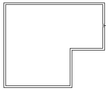
We have a dam with water on one side (let's suppose on the right side). We want to verify the dam from right to left.

Dam1

The best method is to consider a water stratum. A water stratum has 0 porosity, O cohesion coefficient, 0 Fi and 0 weight.

The water bed is on the top of this stratum.

The slide surfaces must continue inside the "water stratum" until the surface.

In this case Geo-Tec B considers the weight and the pressure of the water bed correctly.

Second case:

We have a slope in the water as on a lakeshore or seaside.

Dam2

We want to verify the stability of the slope immerged in the water.

In this case it isn't possible to apply the first method and it's necessary to consider the water as a triangular or trapezzoidal load on the terrain (to consider the effect of the water on the terrain surface) plus the water bed (to consider the effect of the pressure of the water inside the terrain).

There is a special case to simulate a quick emptying of a lake. It's possible to simulate this case deleting the loads on the surfaces and maintaining the water bed on the top level. This because some time is needed for the water inside of the terrain to come out and in the meantime the internal pressure of the water corresponds to the top level of the water bed.

Nonio C

How can imported images be used?

How can imported images be used? Imported immages can be used for a number of objectives, among which some are listed below: - Digitalization of a map with contour lines - Superimposing a design on the survey - Superimposing a survey drawing on an aerial photo - Use of a design as a guide for infill or excavation - Comparison of the terrain model with the map - Comparison of the terrain model with map of property lines

How does Nonio C calculates the terrain model?

How does Nonio C calculates the terrain model? Nonio C constructs a mathematical surface connecting points with line segments to construct triangles. The generation of triangles is also regulated by the maximum distance for triangulation entered in the Preferences dialog box, which requires the program to search for and construct triangles only among points falling between the set distance. For any number of points, there are several possibile ways in which they may be joined by triangulation. If the general guidelines given above are followed and a reasonable maximum distance for triangulation set, the generated model should represent closely the actual terrain conditions. When there are certain discontinuities in the surface, a more detailed modeling process is required. In these situations, connections can be somewhat ambiguous, even for a simple case involving only four points. If automatic triangulation is used in situations like the one above, it can cause erratic results. Nonio C offers the user the ability to impose breaklines (representing lines of discontinuity, such as ditches, ridges, or streets) from which the triangulation can then be completed automatically. The user can locally correct the automatic triangulation and Nonio C recalculate the modified model immediately and automatically.

How does grahic import work in Nonio C?

How does grahic import work in Nonio C? Nonio C imports graphic images in several formats. The PICT import command uses QuickTime and can import all the graphic formats handled by the installed QuickTime Other methods to import an image in Nonio C are Copy and Past and Drag & Drop.

How does DXF import work in Nonio C?

How does DXF import work in Nonio C? Nonio C imports single points,  polygons (in DXF Polyline), faces, which it inserts as points to eventually be united by breaklines. It does not import other elements, such as lines, text, circles, etc. The primary use of DXF importation in Nonio C is to import contour lines from maps and complete 3D models. If you want to import a drawing for other purposes (such as to serve as the base document for a survey project), it's better to import the document first to another program, for example DigiCad 3D, then to Nonio C using Copy and Paste or Drag and Drop.

Domus Cad

Skylights

Is there a technique for adding skylights, i.e. windows on/through a roof or slab? There is a couple of ways of doing this: 1. Using any polygon or curve of any form to "punch" the roof or the slab (select the slab and the polygon on it and execute the command Process -> Punch Slab or click on the equivalent icon of palette #3) 2. Using the scissors to cut the slab into parts and cutting away one of them. Using the light of the sky as a light source (like a room with a window on the north side of the house, where the light of the sky lights the room) isn't possible - you must use one of the 3 types of artificial lighting or sunlight.

Connecting the walls to the roof 2

The User Guide example creates roof slabs, adds upper-level wall segments and then cuts each wall segment to fit under the slope of the roof. Roof design and modification is critical for me; my current project involves re-designing some roof sections on an existing home to accommodate architecture changes to the interior. Basically there are 2 ways to design roofs: as a serie of sloped slabs or as a complex hip roof. There are 2 procedures to adapt the top or the bottom part of the walls to the roofs. This procedures work on a single slab-roof, so if a wall is under 2 different slabs, it is necessary to cut it with the scissors tool and adjust each part to the corresponding slab-roof. You can modify the angle of the roofs and re-adjust the bottom or top parts of the walls in any moment. The height and reference height of the extremes of the walls can be modified also with the corresponding icons on the 3D Palette.

Duplicate elements

Can I draw a pillar, duplicate it at a distance of 2 mt, then duplicate these 2 pillars at the same distance apart to make 4 pillars, then 4 pillars to make 8, and so on. In Domus.Cad there are two different duplication modes: offset and parallel. If parallel operations are enabled (Edit menu), the element duplicates parallel to itself with the value set in the Offset parameters Dialog. If Offset operations are enabled, selected elements duplicate along the X, Y, Z and Angle offset parameters. With multiple duplications, elements duplicate relative to the last duplication. So, if you have a 2 mt X offset and duplicate a selection 10 times, you obtain a series of elements spaced at 2 mt.

How to use the scissors

How to use the scissors? Some general principles regarding the Scissors tool: - The Scissor applies only to the current element. For example, if the current active element is Segments, the scissors only cut segments. - You don't have to select anything. The command is applied to all elements in the current layer and the current type, whether they are selected or not. - You have to cut the whole element, not just a part of it. For example, if you have a polygon, you can't cut just one side, you must cut the whole polygon.

Working with layers

In terms of working with layers and assigning different elements to a layer - ie separate layer for walls, beams, roof slabs, ceilings (assuming a single level building) What do you suggest you set at the reference height for each layer I've been primarily working with walls at level (0000) wall height is say 2900 I set roof ref height at (2900), I've just been working on another project , where I was doing that, but roof's where at different heights, so I made the roof reference height ground level (0000) then made all the roof elements what they need to be (ie pitching off top of wall). Which way do you recommend. You might be taking the separation a bit to far and then it becomes counterproductive trying to manage everything flipping between layers. Separate layers are used primarily for two reasons: 1) to control what you want visible on a layer 2) to separate conceptually different parts of the design (plans, furniture, utilities) We usually separate the roof structure from the floor plan because they're two conceptually different entities, but it depends on what you have to do. If you need to generate garret walls, you need to have the walls and roof on the same layer. So there's really no "best" way. It sounds like you've solved the problem well, doing what worked best for that particular situation. The layer reference heights can all be the same...then you don't have to worry about that anymore and it's just a matter of setting the individual element reference heights.

Domus.cad differences with Autocad

We have been using AutoCad for 2D and Arcon for 3D, but it would obviously be preferable to have only one program. How does DomusCad differ from other programs, say, Archicad or ArchiDesktop? DomusCad is based on totally different concepts from Architectural Desktop. A DomusCad user tends to think in terms of his 'project', because he uses one software to produce one plan, from which he can then develop a 2D drawing, a 3D model, facades, sections, etc. There are more similarities with ArchiCad ad other BIM programs, which, like DomusCad, is part of the Architectural Parametric 3D CAD group. Some differences are highlighted in the first part of our Getting Started manual but there is one fundamental one between DomusCad and other parametric software: we don't believe in 'parametrising to excess'. We don't believe that every single construction element - every wall or window - should be conceived by inserting parameters. In Europe, much designing is done on old buildings, which have infinite varieties of form, dimension and building type. Translating such a wide variety of data ito a large number of parameters in a dialog window - and having to modify them - would be impractical. Our view is that parameters should control 90% of the situation, leaving the designer to free to do as he wishes for the remaining 10%, so within the same drawing there would be fairly automatic parts, integrated with manual ones.

Dormer windows and skylights

Below is one of several possible methods, using the Scissors, a simple but powerful function.  - below is a roof with four walls. Select the Roof/Slab icon and make 3 cuts (shown as red lines. - now modify the color and thickness of the portion destined as a window and reduce the reference height by 5 cm.  This is what it looks like in 3D: - draw 3 more cuts inside the window - and change the internal section into glass - in very little time, we have obtained a skylight Now let's do a dormer window. Begin, as for the skylight, but raise the front end of the window up to form a roof. - build 3 walls around the resulting opening - select Walls and Roof, then execute Generate Garret Walls , to bring the Walls right up to join the dormer window Roof. Finally, how to put several windows into a roof: if you need to make more complex openings in your roof, it is actually easier to create a vertical Wall, insert the windows and then incline the Wall until it becomes a roof. See below: - Create a Wall and insert the Windows - Select it all then use the command from palette no.3, Process menu: Convert to Facets - regroup the facets into one single Object - select the Object and execute ObjRot from the Modules menu as follows: - put the Object on the layer. Here's how it looks in 2D and 3D :

A hexagonal room

I want to create a hexagonal room. I chose 120 degrees and a wall appeared with 120 degree angle. The next wall that I need to build is at 90 degrees. So if I choose Free Angle, how can I build shapes with precise angles? It's similar to the manual method used on drafting machines. If you set the drafting machine to 120 degrees, you can draw elements with 120 and 120 + or - 90 angles. There are several methods to do what you want. By mouse: Change the drawing angle for each wall By keyboard: Select the Pen and the Walls icon Click where you want to start Click on the Polar input box  In the distance and angle fields, input 300 and 0 then click Continue Continue the drawing with the following data: Distance Angle 300 60 300 120 300 180 300 -120 300 -60 By a 2D hexagon: Double click on the Circle button and set the following parameters: Draw a hexagon Select it. Click on the Wall on polygon generation button (palette #3) This is the result

Repeating elements with variations

I have a series of elements which are repeated throughout my drawing, but with different dimensions, so I changed the height of each single element, one by one. Was there a quicker way of doing this? There are several possible procedures. A couple follow below. 1) - Select the elements and group them in an object with the command in the Edit menu. The object is created with a 0 reference height which you can then increase, thus enlarging all the elements inside the object. 2) - Use the offset parameters. In the offset parameters dialog set the z that you want to increase. Enable the offset operations in the Edit menu. Select the elements and execute the Process on Active Layer command (Edit menu).

Furnitures

I want to design a hexagonal apartment starting from its inhabitants and the furniture, then defining the walls. I'd like to do the geometric transformation afterwards. First choose your furniture from DomusCad Folder ->Object Libraries->3D (or 2D) Libraries->Furniture and place it where you wish inside the hexagon. If you want to transform any furniture elements, now is the time to do rotating, re-scaling, deforming, mirroring etc. Next select all the objects and un-group them. Then select everything - walls and objects - and group them in a new object Now you can apply all the geometric transformations to the object

See all the Domus.Cad FAQ