3D View
Shadows
How can I create shadow for objects in 2D or 3D? In DomusCad, cast shadows can only be created using RayShade in 3D. For 2D drawings, use the traditional method of indicating shadows by a hatched or colored polygon. Or try this interesting method : create a 3D view with RayShade, complete with cast shadows. This can then be transferred to a layer which has been rescaled and placed under the technical view. The result is a technical view with colors and shadows. The same can be achieved in plan.
How to illuminate the interior of a building
Please explain how to illuminate the interior of a building. I would like moderate lighting with one illuminated wall, opposite a wall in shadow. Are you using Interactive renderer or Ray Shade? The two renderers work differently. The Interactive renderer doesn't support cast shadows. This means that the light "penetrates" inside the objects and the building, lighting internal objects too. The Ray Shade and OpenGl renderers support cast shadows. This means that if you have an external light, the internal parts of a building aren't lighted and you must insert some point lights inside. When you insert point lights, pay attention to the Z coordinate. Light coordinates are calculated overall, not by layer, so if you put a light on the second floor, the Z starts from ground level, not from the 2nd floor.
Questions regarding the use of 3D View
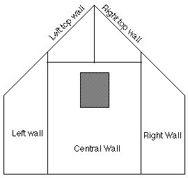
Why does a light inserted in one room illuminate the adjacent rooms as well?
Shadows are not an available option for Interactive rendering, therefore the elements themselves (such as walls and floor slabs) are merely shaded according to their relationship to the light source and do not have the ability to cast shadows on other objects, making it seem as if the light passes through them. It is not possible, for example, to create a completely dark room, even if it has no doors or windows. Use OpenGl and Rayshade renderers for casting shadows.
What purpose does ambient light serve?
Ambient light's primary purpose is to lighten the shaded areas. Without ambient light, all shaded areas would be completely black. A lack of ambient light creates a greatly contrasting image, while a predominance of ambient light creates an image with little contrast. Another purpose is to create a certain atmosphere by changing the ambient light's color.
How do you print the 3D view?
The easiest way is to transfer the view to an unused layer and page it using the normal DomusCad procedure, after which it can be printed.
Is it possible to make a QuickTime film from the 3D view?
It is not possible to make a QuickTime film from inside Domus.Cad, but it can be done using other programs, such as Snapz Pro and Screenium, it is possible to film everything from the 3D View window.
People or animals in 3D view
How can I create people, animals, etc. in a 3D view ? You can either create 3D models (quite complicated), import a 3D model in DWG, DXF and 3DS formats or insert the images people or animals into the 3D view. For example:
- create a 3D view and place it on a free layer
- import the image into DomusCad (e.g. using Cut and Paste).
- Draw a polygon on the image around the part of the photo to be cut. Use PictRot to extract the internal part and set white part transparent.
- rescale the image if necessary, to the same scale as the photo
How to insert a rendering in a photo
How to insert a rendering in a photo? The first step towards inserting a rendering in a picture is to place the Domus.Cad camera in the same position as the real life camera. Place the observed point in Domus.Cad on the point corresponding to the center of the photo. Set the camera angle parameter the same as the lens of the camera. Set the Domus.Cad light direction parallel to the direction of the light in the picture. The sun light generation tool can help you. Set the 3D view background color to white. After that you should obtain a 3D view that is consistent with the photo perspective. Save the image on a free layer. Select the image and with the PictRot module of the Plug In menu change the image to make the white color transparent. Select the image and group it in an object. Place the object on the top of the photo. Resize the object, with the mouse, so that it is perfectly superimposed on the photo.
3D perspective onto a photo of landscape
Is it possible to paste a 3D perspective onto a photo of landscape, in order to show the project's integration into its environment? There are several interesting dxf and dwg models that you can import in Domus.Cad. To superimpose a Domus.Cad rendering onto a photo in Domus.Cad follow the steps below:
- Import the photo in Domus.Cad
- Generate the rendering with a white background
- Save the rendering to a free layer
- Select the rendering image and choose the PictRot command from the Modules menu
- Set 0 rotation, million of colors, 72 dpi and white transparent. Confirm
- Now you can move the rendering onto the photo because the background is transparent.
Textures
I would like to add texture to a 3D perspective, but when I "paste" a fill to the floor, it is visible only in 2D. In the 3D view you can use photorealistic textures. Go to the Colors parameters, associate a texture to a color, activate the texture check box on the color parameters dialog and on the 3D view (far right button).
Add a texture to the texture list
How to add a texture to the texture list? In your Domus,Cad folder you should have a DOMUS-Cad Texture folder. On Windows the Texture folder is inside the Domus.Cad Data folder, on Macintosh there is an alias on the Domus.Cad folder Any image added to this folder will be accessible via the internal texture menu in the Materials Windows of Domus.Cad. If , on a Mac, the texture folder alias doesn't work, you can access the Texture folder directly inside the Domus.Cad Package. To do that, follow the steps below: - Ctrl click on the Domus.Cad icon and on the pop up menu choose the Show Package content command - Open the Content folder - Open the MacOs folder - Open Domus-Cad Data folder - Open the Domus-Cad Texture folder - Drag your Texture to the Domus-Cad Textures folder
How to use specular color and coefficient?
How to use specular color and coefficient? All materials have a diffuse color and a specular color, which can be different. If so, the color of the material changes depending on the position of the light. The specular coefficient changes the aspect of the material, giving it a more plastic or metallic appearance. With RayShade an high specular coefficient generates a mirror effect.
Interior lighting
The rooms of my building, which have no external lighting, are completely dark. Is there any way of defining natural lighting for the whole interior, valid all through the evolution of the 3D version? Or must I define the light source as I go? Natural lighting is really all about shadows - more light means fewer shadows. It all depends on the type of renderer you are using. For example, the interactive renderer doesn't support cast shadow, so if you use an external light, it lights the interiors too. The RayShade renderer supports cast shadows, so the light doesn't penetrate across the surfaces and doesn't light the interior - you have to put other lights in the building.
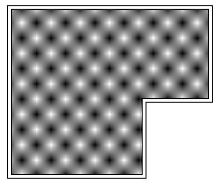
 The No Fill option is assigned to all the rectangles, circles, polygons and curves drawn after the choose.
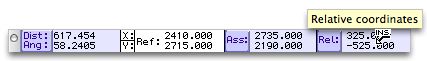
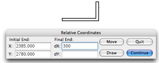
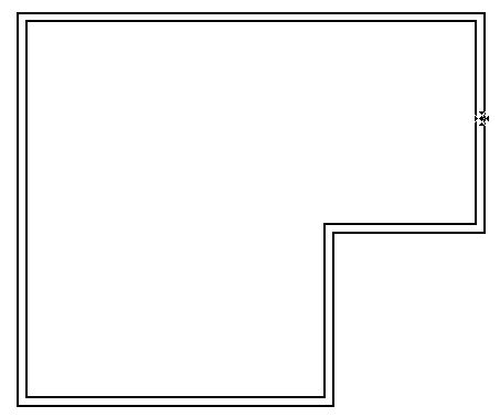
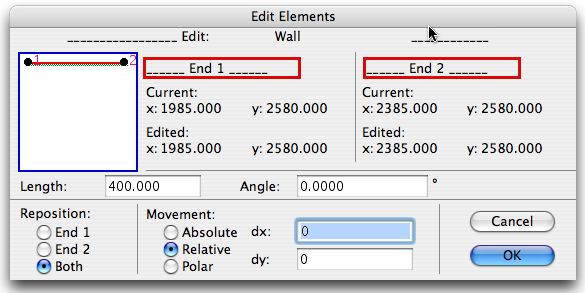 You can change the length, the angle and move the element.